|
| |
| This article was printed in two parts in Computer Technology Review. The first part appeared in the December 2001 issue (Vol.21, #12). The second part appeared in the January 2002 issue (Vol.22, #1). Below are both parts. | |
| Eliminating the reel motor position sensor in a tape drive. | |
|
Peter Groel, Mountain Engineering II, Inc. | |
|
| |
|
As the components of choice, solid-state electrical instruments have all the advantages of the tape drive industry's three prime directives: they are reliable, small, and low-cost. The problem with the average tape drive design is that engineers do not always get a choice in determining which components to use. So replacing mechanical components with electrical components remains, in many cases, an unreachable goal. | |
|
A tape drive consists of many more mechanical components than the average disk drive. There are the cartridge loading and threading mechanism, two reel motors, the head actuator, and several sensors, to name but a few. These irritating mechanisms are the main obstacle to our desire to improve the reliability, while at the same time reducing the cost and the size of a tape drive. As long as so many mechanical parts linger on in these designs, we will never see the advances in tape drive technology in orders of magnitude as the disk drive industry has already produced. | |
|
This article discusses how to replace one of those mechanical components, the reel motor position sensor, with solid-state components. Mid-range and high-end tape drives use brush-less DC motors. The rotational position of the tape reel motors must be known for two reasons. First, the electronics for the motor commutation needs to know the rotational position of the motor. Second, the speed of each motor must be tightly and independently controlled. Components that sense the change of the motor position over time measure its speed, and thus allow it to be controlled. While replacing one motor sensor does not solve all our problems, and it still leaves many mechanical parts remaining, it is a decisive step in the right direction. This solid-state electronic substitution makes a significant contribution to the tape drive industry's overall prime directives in tape design. | |
| THE CURRENT STATE OF THE TECHNOLOGY | |
|
Most newer tape systems use tape that is pre-formatted with a servo track by the media manufacturer. Examples of these systems include the IBM 3590, LTO, SDLT, and the STK 99840/9940. The servo track is, in most cases, read by a special read element in the read/write head (with the exception of Quantum's SDLT). One of the advantages of the servo track is that it can be used to measure the speed of the tape. This measurement is quite accurate and is taken directly at the read/write head, the area where the tape speed matters the most. The use of a servo track to sense the tape speed greatly improves tape speed control, but it still cannot eliminate the need for a motor speed sensor. | |
|
Unlike a disk drive, tape drives must control the motor speed at all times, including those times when the servo signal is not available. This occurs when tape is accelerated, when it is decelerated, during a high-speed operation (rewind-and-locate), and even when tape is stopped. The requirements for the resolution of the speed sensor may be relaxed when the read/write speed is controlled with the feedback from a servo track, however an accurate sensor is still needed. | |
|
Hall-effect sensors are widely used, but they have severe restrictions. The resolution is limited by the total number of sensors. The accuracy of the position sensing is limited by the accuracy of the position of the sensors and by the gain tolerances. In fact, because of these restrictions Hall-effect sensors are used mostly only for the motor commutation, and an additional sensor system must used to measure the motor speed. |

|
Hall-Effect sensors are commonly added to the motor driver card to sense the motor position for commutation. | |
|
Optical sensors are the preferred choice for motor speed sensors. They consist of optical as well as mechanical components. The optical unit shines light beams through the slots of a code wheel that is attached to, and rotates with, the motor shaft. A photo sensor detects the interruptions as the slots pass by. Slots are electrically counted as they move through the sensor and this count corresponds to the accumulated angle of the rotation. | |
 |

|
Optical sensors consist of an optical sensing unit and a rorating code wheel attached to the motor shaft. |
The combined height of the cartridge, the motor, and the optical sensor can easily exceed the height of a half-height drive. |
|
Optical sensors are quite accurate and have high resolution (resolution of 500-2000 slots-per-revolution is typical). They can, however, easily cost just as much as the motor to which they are attached. In addition, they are sensitive to ambient light and susceptible to contamination. Finally, it is problematic that they also require space below the motor. The optical sensor is attached to the shaft of the motor and is usually mounted below the motor. This requires space in an area where we can least afford it. The combined height of the cartridge, the supply motor, and the sensor can easily exceed the maximum height of a half-height drive. | |
|
When this accurate optical sensor is used, why do we even need the Hall-effect sensors for commutation? | |
|
Actually, we don't. The position information required for the commutation can easily come from the optical sensor. There is an issue with initialization, since we do not know the initial position of the motor on power-up. But this question can quite easily be answered by measuring the winding inductance on power-up. For tape drives, we prefer to measure the winding inductions with a modified current pulse (current injection) method (explained in more detailed below) that is safe to use even when tape is loaded on power-up. In several tape products we successfully used an optical encoder in conjunction with this initialization method. | |
| This article is the second in a two-part series. The first part appeared in the December issue of CTR. | |
|
| |

|
|
Back-EMF sensing measures voltage across undriven winding. | |
|
Back-EMF sensing measures the voltage across the unused winding in a typical brush-less DC motor with a three-phase, Y-stator configuration (Figure 1). Current is switched to two of the three windings at any time. As the motor rotates the drive windings and the sense windings are switched. The signal amplitude measured at the unused winding is proportional to the motor speed. This simple method works well when the motor turns at a constant speed. It does not work at all, however, when the motor turns slowly or is stopped. For tape drives, where the speed and motor position must be controlled at low speed as well as when the motor is stopped, back-EMF sensing is not at all useful. Thus far it has been used in disk drives and fans, but not in tape drives (Figure 2). | |
|
There are several patents and proposals that involve adding a sense winding to the motor. This technique does not meet with our stated goals because it adds manufacturing cost. Nor does it meet with our preference that the sensor-less motor driver be able to function with any motor without requiring any modification of said motor. We know of no practical application where this method could be employed. | |

| |
The Back-EMF voltage can be used to determine the motor speed, once the motor is close to nominal speed. | |
|
The next unsuitable manner to eliminate the sensor is to measure the impedance change of the motor windings by injecting a high-frequency sense carrier, or probing with current pulses. The motor winding impedance varies with the rotation of the motor. It should be possible to measure this impedance change and thereby get an indication of the motor rotation. | |
|
A high frequency sense carrier operates by imposing a high frequency signal into the drive current. There has been some academic discussion of this method, but it has never been implemented. There are several problems with this approach so at least for now it should probably remain in the realm of theory. | |
|
The rise and fall time of current pulses varies with the winding inductance. In addition to measuring the rotational position of the motor, this current pulse probing method can also detect the polarity of the magnetic motor pole when high currents are used. It can therefore be used to distinguish between the two 180-degree half-cycles (Figure 3). Current pulse probing also works well when the motor is stopped and when the motor is turned off. In a tape drive application we can do this when tape is not loaded and when it is not under tension. Use of current pulses when the motor is running is unacceptable in a tape drive, however, because it disturbs the motor torque and produces undesirable speed and tension variations. | |

| |
The rise and fall time of current pulses varies with the winding inductance, which is an indication of the motor position. | |
|
In a well-designed servo system the injection of current pulses can easily be implemented in firmware. For initialization on power-up when a tape is present, the method of pulse probing still can be used, but we must be careful not to move the motors. Motor movements to any significant degree could damage tape. We have found that the combination of two modifications works quite well. First, we keep the width of the pulses short, to about 300 ms21. Second, we reverse the polarity for every other pulse through the same winding, which cancels any small motion that may result from the first pulse. | |
| Eliminating the sensor-the right way | |
|
We have shown above that there are several methods with which to sense the rotational position of a motor without using a sensor. Back-EMF sensing is commonly used in disk drives and in fans. But none of these methods work well for tape drives. Does this mean we cannot do what the disk drive industry is doing? | |
|
In the following discussion we will show that we can indeed use a sensor-less method. But, as usual, things are a bit more complex with tape drives, so we need to be a bit smarter to achieve success. The solution to the above problems requires a new technology. Our new approach measures the motor windings impedance ratio. Our design includes use of a reference network to simulate the voltage across an ideal winding with no impedance variation. The two driven motor windings form a voltage divider. Knowing that the impedance variations will cause the center note to vary, our technique compares this center note to the reference voltage. This comparison now yields our sense signal. The sense signal for each phase is roughly sinusoidal (Figure 4). | |
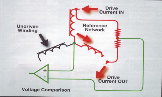 | |
Impedance ratio measurement compares the voltage from a reference network to the center node voltage. | |
|
The sense signal depends on the ratio of the impedance of the two windings. Using the measurement of the differential impedance is very advantageous. It compensates for variables that affect both windings, such as the drive current, the drive voltage, and temperature variations. The impedance pattern is repeated every 180 electrical degrees. (One turn of the motor = 360 electrical degrees x the number of poles). It is not possible to distinguish between the two half-cycles unless the motor is initialized. Once initialized, the position tracking is incremental, and therefore initialization only needs to be done once, on power-up. We have found that current pulse probing is quite effective for this purpose. | |
|
At higher speed, the back-EMF influences the center note voltage. The effect of the back-EMF is predictable and can be compensated for. It is, however, easier to simply revert to using the back-EMF for the positioning measurement once the motor reaches medium-to-high speeds. | |
|
Our new sensor-less motor driver uses current pulse probing to initialize the motor after power-up. The current pulses do not rotate the motor, so this method can be safely used even if a tape was loaded on power-up. Once the tape has been accelerated to moderate-to-high speeds, we use back-EMF sensing to determine the motor speed. | |
|
We use impedance ratio to measure rotational speed of a motor at all other times. This includes the acceleration time, the deceleration time, when tape is stopped and is under tension, and when no tape is loaded. | |
|
This technique also has general utility to the industry and need not be a narrow application restricted only to tape drives. It can be used in any situation where a motor position needs to be measured at variable motor speeds. Printers and robotic applications are only two examples of a potentially versatile technology. | |
|
Our approach required the addition of intelligence to the motor driver electronics. Adding more intelligence and removing mechanics is always more efficient in the world of high technology. Remember, in Oz the Tin Man had two problems: he had no brain, and he had mechanical parts that constantly needed maintenance. Not only have we given our "Tin Man" tape drive a bit more brain, we have also made some of his moving parts obsolete. | |
| Computer Technology Review December, 2001 & January, 2002 | |
| Peter Groel is president of Mountain Engineering II, Inc. in Longmont, Colorado. MEII specializes in tape drive design and in the development of intellectual properties related to tape drive design. Mr. Groel can be contacted at MEII by phone 303-651-0277 ext. 11, or via email at peterg@mountainengineering.com.
| |
| MEII Home | The Company | Services | Technologies | Intellectual Property | Products | Publications | Contact Us | Visit Us |