|
| |
| Porous rollers offer new approach to tape-path design challenges | |
|
New challenges require an examination of the possible solutions that can be applied to the task of guiding tape | |
|
Peter Groel, Mountain Engineering II | |
|
A number of challenging problems face designers of tape-path systems for next-generation tape drives. For example, tape speeds have increased from 2 meter/sec to today's LTO tape speeds, some of which move at over 6 meters/sec. Tapes are also thinner and more fragile. Whereas older 9-track tapes are 48 microns thick, some tapes in use today are a scanty 5 micrometers-a reduction in tape thickness of almost an order of magnitude. Contamination is also a greater concern. When recording to a 9-track tape, contamination of the size shown in Figure 1 would not have affected even one track, but now, by the time a 384-track tape is written, a single piece of the same size debris can affect over 8 tracks, greatly increasing the error rate. | |

|
 |
|
Drive size is another critical issue. Newer tape drives are 51/4-inch form factor or smaller, leaving barely any space for other essential tape-path elements. | |
| BEARINGS, BEARINGS, AND MORE BEARINGS | |
|
Bearings are key elements of the tape path, not only responsible for guiding the tape along an often circuitous path, but also for stabilizing it as it approaches the read/write head. Three types of bearings are traditionally used: hydrostatic, hydrodynamic, and roller. | |
|
Hydrostatic air bearings use compressed air to separate the tape from the bearing, requiring bulky pumps and filters. They are also expensive, and today, hydrostatic air bearings are primarily used only as low-flow air bearings in specialty applications. | |

| |
|
In small drives, hydrodynamic bearings are more commonly used, as they are suitable for high tape speeds and have no limitation on how fast the tape can be accelerated. Hydrodynamic bearings have their own problems, however, including tape wear and "stickage." For example, as the tape moves over a hydrodynamic bearing, it is separated from the bearing by a film of air generated by the moving tape itself. As the tape speed decreases, however, the air film dissipates, and the still-moving tape contacts the bearing surface. This friction will eventually damage the tape and microscopic particles will also be scraped off the tape and deposited on the bearing surface, as well as the tape. | |
|
Flying length is also limited with hydrodynamic bearings. Since the air dissipates toward the edges of the tape after some distance, it will be insufficient to maintain a separation between the tape and the bearing. For example, with a half-inch tape, you can expect a maximum flying length of maybe one inch. | |
Another unpleasant artifact of hydrodynamic bearings is "stickage." Stickage occurs when tape sticks to the head or to other tape-path components, and is especially common in humid environments. | |
|
A final problem involves the surface finish of hydrodynamic bearings. Surface finish selection is critical but contradictory since, in order to minimize stickage, a rough surface is desired while, to minimize tape wear, a very smooth surface is preferable. Finding just the right compromise of materials can be difficult and expensive. | |
Roller bearings, also known as rotating guides or rollers, can have flanges and may be flat, or crowned. Rollers are mounted on precision ball bearings, and are employed to save space primarily in smaller form-factor drives. | |
|
Unlike hydrodynamic bearings, roller bearings produce very little tape wear because there is no relative movement between the roller surface and the tape. Second, because the rollers can rotate, they are not susceptible to stickage even in areas of high humidity. Contamination is also less of an issue because debris tends to be moved away from the roller during operation. Rollers also mass-dampen the tape path, a highly desirable effect since a dampened path allows higher recording densities, and newer recording technologies such as PRML require greater stability. | |

Rollers have their problems as well, however. First, rollers tend to be eccentric, i.e., they rotate unevenly around their bearing. Second, an effect known as "barber poling," caused by a roller that is not exactly perpendicular, is also an issue. Bearings can also vibrate, and the mass of the roller can limit the amount by which one can accelerate the tape. Finally, just as rollers offer a tape-wear advantage over hydrodynamic bearings, tape flying is a big disadvantage. | |
| TAPE FLIES OVER ROLLERS | |
|
In short, the moment tape begins to fly, most of the advantages that rollers have over hydrodynamic bearings are entirely lost. When tensioned tape (e.g., at 1 Newton) moves at a low speed across roller bearings, the spool rotates smoothly around the shaft. However, as the tape speed increases, the air currents moving with the tape cause an air film to develop between the spool surface and the tape. This separation is undesirable for a number of reasons. | |
First, the air film is turbulent and causes the tape to flutter. This is an obvious problem since to accurately record and read data, the tape must be stable at the recording head. This is particularly true with today's new recording technologies that use increasingly small bit cells of data. | |
|
Also, as mentioned, the dampening effect of the roller being in contact with the tape helps to stabilize the tape speed. This is particularly desirable as it helps compensate for tape speed variations caused by other portions of the tape-drive system. For example, interlayer slip in the cartridge hub is one cause of sudden tape-speed variations. | |
Loss of tape-to-spool contact also causes tape tracking to be lost. Tachometers are often used to measure tape speed, but if the tachometer is attached to the roller, and the tape isn't touching it, the roller will slow down and no longer give a true indication of tape speed. | |
| ROLLER TESTING | |
|
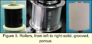
To evaluate how various roller types handle tape flying and tape deformation issues, three different types of rollers were tested under controlled conditions. The tests analyzed rollers with three different surfaces-solid, grooved, and porous. | |
Tape speed was varied from 1 meter/sec to 12 meters/sec, tape tension was kept constant at 1 Newton, and the wrap angle was variable from 10° to 120°. Wrap angle (the angle at which tape wraps around the roller) is important because tape tends to fly later (i.e., at a higher speed) when wrap angles are increased. Though designers generally don't have much freedom in placing wrap angles because of limited space, whenever a choice is possible, it's generally best to keep it as high as possible to prevent tape flying. | |
|
Solid-surface rollers are widely used, and are usually made out of some type of molded plastic or metal. The rollers contain a bottom flange and a top flange to limit the movement of the tape off the spool. Though solid-surface rollers don't damage or deform tape, they do generate tape flying. | |

Solid-surface rollers performed least well in the tests. Though the tape didn't fly when the speed was kept at 1 meter/s and the wrap angle at 10°, when it was increased to 2 meters/sec, it was necessary to increase the wrap angle to 70°. At the maximum wrap angle of 120°, the fastest allowable speed before tape flight was 3.25 meters/sec. | |
| GROOVED ROLLERS | |
|
One approach to dissipating the air film between the tape and roller has been to add grooves to the spool surfaces. At medium speeds these grooves can be quite effective in preventing the development of an air film, but at high speeds the grooves can no longer dissipate enough air, and the film will still appear. | |

Under certain circumstances, grooves can actually also damage the tape itself. Thinner tapes, in particular, will indent into the grooves as the tape moves across the spool causing permanent damage that may result in a high number of recording errors, or an inability to record at all. Though the venting capacity of the grooves increases with their size and number allowing for higher speeds, they will also produce greater tape damage. | |
|
Daly has patented a spool with grooves in an oblique orientation to minimize tape deformation (#5,199,168). While effective, the helical groove caused the roller bearing to guide the tape differently in each direction. It also caused instability in the tape, particularly when the direction of movement changed frequently, giving it limited usefulness in tape-drive applications. | |
Grooved rollers performed fairly well in the comparative testing. At a tape speed of about 4 meters/sec, the tape did not fly below a wrap angle of 10°. When the speed was increased to 6 meters/sec, however, a wrap angle of 50° was needed, and to reach 12 meters/sec this was increased to 120°. | |
|
Although the grooved rollers did prevent tape from flying at higher speeds, they deformed the tapes, sometimes to disastrous degrees. Thin tapes, especially those as thin as 5 micrometers, suffered the worst. Grooved rollers also introduced an undesirable lateral bias, depending on which direction the tape was travelling. | |
| POROUS ROLLER | |
|
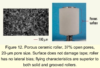
The porous roller (patent pending) developed by Mountain Engineering II (Longmont, CO) is a tape roller bearing made from porous material that allows air to flow through the spool surface and prevents the development of an air film between the roller surface and the tape. | |
|
The spool can be made from molded ceramic, plastic, or sintered metal. Ceramic surfaces are more rigid than plastic allowing the spool wall to be quite thin; they are also conductive for ESD protection. For magnetic data tape, the spool material should be nonmagnetic-such as carbide, alumina, or stainless steel. None of these materials impact tape integrity or adversely affect the guiding ability of the roller. | |
Spool porosity should preferably be in the range of 30% to 50% open, having pores with an average diameter of between 50-250 µm. Pores can either be straight through the spool (from movement surface to interior surface) or they can be more sponge-like with interconnecting pores. | |
|
The porous roller tested had a plastic surface, a pore size of 150 µm and 50% open pores. At a wrap angle of 10°, tape did not begin to fly until a speed of over 5 meters/sec. At a tape speed of 8.5 meters/sec, the wrap angle was increased to 65°, and by increasing the wrap angle to 110°, the tape speed could be increased to over 12 meters/sec without flying. | |
Since the tape remained in contact with the spool up to very high speeds, the dampening effect also increased tape stability, which as mentioned earlier will allow the use of new, small bit-cell recording technologies. | |
|
In summary, the MEII porous roller prevented the development of an air film between the roller surface and the tape. The pores are small enough that tape damage didn't occur, even with the thinnest of tapes, and the tape remained in direct contact with the roller, even at high speeds. Another advantage of the porous roller is that a tachometer can be attached to it, and since the spool spins at the same rate as the tape movement, it is possible to accurately and consistently measure tape speed by measuring spool speed. | |
| DATA Storage June, 2001 | |
| MEII Home | The Company | Services | Technologies | Intellectual Property | Products | Publications | Contact Us | Visit Us |